Inspired by the Jointer made by FreddyS published at Lumberjocks.com/Projects/45954 I made my own version using a Black & Decker power planer model KW712-QS


Building the fence

The plan was to mount the Planer in an inverted position and extend the infeed and outfeed sections so as to provide greater stability to the part being jointed. The build is in four steps
- Mounting the planer
- Building the fence
- Making the infeed and outfeed tables
- Making the blade guard
The planer is mounted on four supports. The planer had a slot in the front for fixing a rabbiting fence. I had a saw guide which was the perfect size for the slot. Since this guide was not being used, I cut off a length slightly bigger than the width of the planer so that the planer could be held with these extensions


The front support is 3" wide and shaped to the contour of the planer. Slots for holding the support extensions made in the previous steps were cut. The aft supports were also cut to match the planer's profile.


The four support legs were mounted on the base using pocket hole joinery.


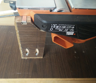
The fence is a 4" x 23" piece of veneered particle board (taken from an old computer table) mounted on two pillars. The fence is attached to the pillars using two bolts for each pillar. These bolts screw into T-nuts embedded inside the pillars.

The pillars are made of three layers of 2" x 11" strips of particle board sandwiched together. The T-nuts are affixed on the inner panels of the pillars and the three strips screwed together to make one pillar


The assembled fence is mounted on the plywood base using pocket holes. The edge of the fence just touches the edge of the face plate of the planer.

Minor adjustments for ensuring that the fence is at right angle to the planer face plate can be done by adding a shim under one of the four fence mounting screws. In my case, I had to put a washer under the top mounting screw on the out-feed side.

Making the in-feed and out-feed tables
The in-feed and out-feed tables are held on two blocks. Each block is made of three layers of particle board. The in-feed block is 5" x 4" while the out-feed block is 4" x 4".
The in-feed and out-feed tables can be moved up and down to enable finer adjustments to the in-feed and out-feed surfaces. Each table is held to the block using four shop made thumb screws which tighten into four T-nuts embedded in the inner sides of the sandwiched support blocks. Relief slots were cut in the center panel of the blocks to allow space for the T nuts.

The three panels of each block were screwed together and tested for proper fit of the thumbscrew bolts.

The thumbscrews were made by attaching knobs to the bolts. The knobs were circles (2" dia) cut out from a 12mm piece of plywood using a circular saw. T nuts were affixed to these knobs for holding the bolts firmly.

The tables were made using pieces of chipboard for the vertical sides and plywood for the horizontal section. The vertical pieces are 5" x 7" for the in-feed table and 4" x 7" for the out-feed table. The width of the top horizontal piece is 1mm wider than the width of the sandwiched block.

Slots were cut in the vertical panels to enable up/down movement of the table. After marking the exact position of the thumbscrew holes, slots extending 1" vertically were cut on the router table.

The in-feed and out-feed tables were mounted on the base plate using pocket hole screws.The two tables were mounted in alignment with the planer in-feed and out-feed surfaces.

To allow for a slick surface to the in-feed and out-feed tables, two pieces of high density plastic (cut off from a kitchen cutting board) were mounted on these tables.

Making the blade guard
The swing action of the blade guard is achieved by using a door hinge.

The hinge is mounted on a 1" wide strip screwed to the vertical planer support leg. The "door" is a 4" x 4" block of plywood.


The blade guard plate is made of 4" x 6" 6mm ply. The front corner is rounded. This plate is the screwed on to the "door".


For auto closing the blade guard attached one end of the spring to the support leg and the other end to the "door".


Sketchup Model
Using the Jointer
Dimensions


Nice job. I am adapting a 4 3/8 planer for a jointer and may use some of your ideas. Thanks
ReplyDelete